


Troubleshooting Guide
Continuous Blender Troubleshooting
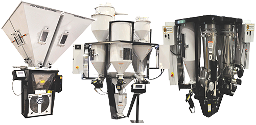
For troubleshooting purposes, the Process Control blender should be viewed as two separate systems:
- the Weigh System which precisely weighs the material and transmits the readings to the operator station
- the Feeder Drive System which receives speed change commands from the operator station and controls the feeders accordingly.
Some hints about checking each of these systems as well as an important point about grounding flex hose can be found below.
The Weigh System
In order to produce accurate blends, the weigh system must be able to accurately measure the amount of material being removed from the hopper (the “weight loss”). It is best to check the weigh system while the blender is paused. Each hopper weight can be viewed on the display using MONITOR. No weight fluctuations should be seen during a paused condition. Any fluctuation indicates either:
- Hopper mechanical interference. This is the most common cause of inaccurate weight readings. Inspect each hopper very closely to see that nothing is touching the hopper. Common points of mechanical interference are:
- the end of the auger tube touching the sample chute or cascade chamber;
- the loadcell overload protection screws touching the loadcell;
- the hopper drain tube touching the blender loadcell platform;
- flexible hoses or material lines touching the hoppers. These points are normally in close proximity to the weigh hopper, but should not touch unless something has shifted during shipment or use.
- Nonlinearity of the weigh electronics or loadcell. Linearity is described as the weigh systems ability to measure weight accurately over the entire range of the loadcell. To perform this test, view the hopper weight on the display using MONITOR. The hopper may have material in it. Hang a calibration test weight on the hopper and verify the hopper weight rises by exactly that amount. A hopper which reads 12.25 pounds of material prior to hanging a 10 pound test weight should now indicate 22.25 pounds. Any deviation more than 0.01 pounds from the target value indicates the need for hopper calibration or possibly a defective loadcell. Check with PCC Service for a quick way to test a load cell.
The Feeder Drive System
The feeder drive system for each hopper should be tested for stability and linearity. This is best accomplished with the weigh hopper paused and emptied of material. The user must first enable the manual backup mode on the blender. This will allow for manual speed setting of the feeder motor being tested, which can be verified using a hand held tachometer positioned directly onto the drive end of the auger shaft.
The user should first set the manual speed setting to 100% and verify the auger RPM indicates the motor gearbox maximum RPM. The user would then change the manual speed setting to 50%, 25% and finally 10% motor speeds, all the while measuring and recording the auger shaft RPM. The measured values should be directly proportional to the percentage of the maximum motor gearbox RPM. Additionally, the measured RPM values should be stable during the test. An RPM value which fluctuates by plus or minus 2 RPM is not stable and could cause poor metering performance during gravimetric operation.
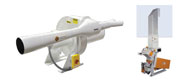
Ground Material Flex Hose (see diagram)
One common cause of blender performance problems is improper grounding. The static charges produced by the material moving across the inside of the flex hose can be enormous. This is especially noticeable when humidity is low allowing high-voltage arcs to occur. Grounding of material lines should be taken very seriously. Failure to properly ground material flex hoses is a hazard to operator personnel and electronic equipment. Material hoses must be grounded to a good earth ground located AWAY from the blender and receivers. This includes material lines positioned vertically between a surge bin and knifegate assembly. Remote mezzanine mounted blenders cascading material over a vertical distance through flex hose must utilize grounded hose as well. Material flex hoses supplied by PCC include a static discharge wire enclosed in the flex hose length. This wire must be stripped back and grounded to the fixed material line or some supporting structure which is connected permanently to a good earth ground. At no time should this wire to be attached to anywhere on the receiver or blender as this simply discharges the static directly into the receiver and blender frame causing likely damage to the electronics. Installations utilizing material hose without a static ground wire can be wrapped with a bare braided wire like a barber pole or candy cane over the entire length of the material hose. Hose clamps are suitable for holding such a wire in place and again the wire must be terminated to a good earth ground away from the blender and receivers.
Additional Troubleshooting Tips:
Additional troubleshooting tips are available in each of our equipment manuals. Visit Manuals and Software Download to view these items.
How-To Videos:
| Description | Size | File | Updates |
| How to Calibrate the Guardian 2 Blender | 9.2 Mb | Calibrate.wmv | Apr 5, 2012 |
| How to Modify Default Alarm Actions on the Guardian 2 Blender | 7.3 Mb | Alarm.wmv | Apr 5, 2012 |
Using VNC with the Guardian 2 Blender: